| Home > Air/oil modulation lubrication system with mini pumps working |
|
 |
|
Air/oil modulation lubrication system with mini pumps working
Description:
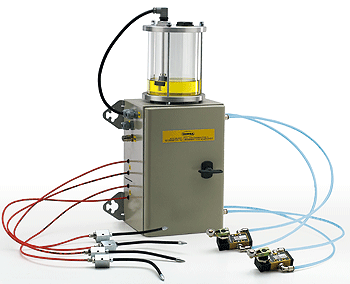
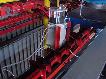
The items which compose the plant are assembled in a metallic unit. The plant looks compact and easy to place. Our system’s planning and building follow the ultimate lubrication technologies, in order to avoid wastes and to respect work places.
It is a modulation system and for this reason it is possible to compose different plants varieties. Each modulus corresponds to a lubrication point and it is controlled by a pneumatic valve with mechanical gear. Then each modulus is composed by an air/oil mixing base and by a mini pump.
The carrying out is very simple. The only items to be placed are:
1) metallic unit.
2) pneumatic valve.
3) nozzles.
Its points of force are:
- automatic lubrication.
- mixing base income air control and mini pumps outgo oil control.
- long lasting guaranteed.
|
|
AIR/OIL regulation:
The air/oil regulation is manually made.
- AIR: rotate in a clockwise direction the suitable metal ring of the regulator put on the mixing base in order to reduce the entry.
- OIL: rotate in a clockwise direction the suitable knurled ring placed on the mini pumps in order to increase the entry.
Advantages:
- During the working, previous regulation of the air/oil mixing, no oil mist in work-zone is generated, according to the recent laws regarding health and safe on work places.
- Targeted lubrication, thanks to proper flexible noozles which maintain the given position, decreasing lubrificant consumption.
Safety:
- The plant is equipped with a level drill connected to the pneumatic electro-valve which in case of lubricant lack stops the working.
- By customer’s choice it is possible to connect the OUT signal to a PLC or to an acoustic or visual signal.
- It is possible to feed the lubrication plant under the same tractor electric line. In case of machine stop the plant working stops.
|
|
|
|
 |
|
Electrical connections:
- The metallic unit is equipped with its proper holdfast items. Connect the feed cable to the IN switch.
- The OUT switch is for the Outgoing signal (see safety notes).
Pneumatic connections:
- Connect the 8 mm polystyrene feeding cable to the AIR pneumatic clutch. For a correct working of the lubrication system give 5 to 8 Bar compressed air.
Dis. di riferimento: dis. 1 con esempio di schema cod.: PN 2+2.
|
|
Schedules:
- Schedule 1: are described the plant’s technical qualities.
- Schedule 2: are described some of the different plant varieties that we are able to offer. It is possible to figure out customized schemes in order to satisfy any need and any appliance. By customer’s choice it is possible to have a 1.5 or 3 lit. capacity oil tank.
- Lubrication noozles are given at a standard 150 mm size. On request we are able to supply different lengths in order to easy the reaching of hard to lubricate spots. They are equipped with a retaining embody valve to guarantee long lasting.
|
| Schedule 1: Technical specifications |
|
| COMPRESSED AIR |
|
|
|
| Operating inlet pressure |
5-8 bar (73.5 - 117.6 psi) |
|
|
| Maximum quantity of particles in suspension |
15 mg/Nmc |
|
|
| Maximum diameter of particles in suspension |
0.05 |
|
|
| Dew point |
2°C (35.6°F) |
|
|
| Max quantity oil in suspension |
5 mg/Nmc |
|
|
| SOLENOID |
|
|
|
| Solenoid voltage |
by customer's choice |
|
|
| Maximum voltage |
by customer's choice |
|
|
| SONDA DI LIVELLO |
|
|
|
| Max voltage filling level indicator (commutable) |
220 V 50 HZ |
|
|
| Massima corrente solenoide |
by customer's choice |
|
|
| MODULAR SYSTEM |
|
|
|
| Capacity single modulus |
1 - 35 mm³ |
|
|
| Operating temperature |
-10 – 80° C |
|
|
| Humidity |
95 % MAX |
|
|
| LUBRICANT |
|
|
|
| Lubricants admitted |
Minerals – Synthetic not aggressive
Not inflammable Not toxic Not harmful
|
|
|
| Operating lubricant viscosity |
30 – 320 cSt (mm²/s) a 40° C |
|
|
|
|
| THE AIR MUST BE FILTERED AND DRY |
|
| Description |
Code |
|
| N. 2 modules executed by n.1 switch limit |
PN 2 |
|
|
| N. 4 modules executed by n.1 switch limit |
PN 4 |
|
|
| N. 2+2 modules executed by n.1+1 switch limit |
PN 2+2 |
|
|
| N. 4+2 modules executed by n.1+1 switch limit |
PN 4+2 |
|
|
| N. 2+2+2 modules executed by N. 1+1+1 switch limit |
PN 2+2+2 |
|
|
| N. 2+2+4 modules executed by N. 1+1+1 switch limit |
PN 2+2+4 |
|
|
| N. 2+2+6 modules executed by N. 1+1+1 switch limit |
PN 2+2+6 |
|
|